|
|
Post by jspbtown on Oct 13, 2011 12:26:55 GMT -5
While precaution is always good I can tell you from experience that this is not really that hard. Of course if you are uncomfortable in doing it then by all means don't. Just like anything else.
Looking at the quote I found this part really amusing: "or kill you if you put your head under the plate".
Really? Do you realize that you would have to basically lay under the car, with your head under the rear wheel area, all while prying the torsion arm off the torsion bar. Not only would you have to be a circus performer but you would have to be absolutely STUPID as well.
Its silly things like that which get there own life on the wonderful web. People see it and believe it without thinking about it.
Here are the facts....the arm is under pressure. It will want to snap downward. The only thing preventing it from snapping downward is a little ledge that it rests on. If while your removing the bolts that connect it to the rear axle area it "may" slip off the little ledge and shoot downward. So common sense tells you not to have your feet (or your frickin HEAD) anywhere under that arm. If you support it with a jack it won't do that.
So Donnie, don't do it if your not comfortable with doing it, and definitely watch your guru do it when he does. Because afterwards I bet you will say "Geez...that wasn't that hard".
|
|
|
|
Post by jspbtown on Oct 13, 2011 11:04:31 GMT -5
probably the aluminun spacers that have the 1 offset bolt. I have them on my Avenger but am taking the rear ones off since they push my rims out to far.
Just take some measurements off the rim regarding the backspacing so you know what sized rims to get.
|
|
|
|
Post by jspbtown on Oct 13, 2011 8:43:06 GMT -5
The rear is real easy. I hope others will chime in because its been a while so I may forget some steps.
Where the rear arms attach to the axle there are a few bolts. First mark the relationship from the arm to the mount near the wheel. I use a cold chisel or hack saw to make a little line across both the arm and the rear bearing assembly. That was you can just re-align the marks. I then put a good size hydraulic jack under the end of the arm. Some people use a special tool, others use a chain. The reason being that those arms will want to spring down pretty violently when released. Then remove the bolts.
Then remove the cap that covers the torsion bars on the other end of the arm. I would then mark the relationship of the arm and the bar. You can then GENTLY pry the bar off of the lower stop that its resting on. Once its off the stop you can release the pressure on the arm by lowering the jack. Once the pressure is off the arm should come out and you can re-index the arm on the torsion bar.
The torsion bar has inner and outer splines. Each set of splines adjusts the bar in different increments. I would just go 1 notch on the outer part. Remember...you want to move the arm upwards. A little goes a long way. Do this for both sides. Then re-install the cap (sometimes you need a longer bolt to pull the cap in. Use the longer bolt to pull the cap in, then install a stock bolt, then another stock bolt, then remove the longer bolt and use a stock bolt). After the cap is on jack the arm back up onto the stop and re-install the arm onto your rear axle housing.
Overall its not hard. Use marks to establish your baseline. Some people use an angle finder on the arm (measure after you drop it off the stop) and then index it up and measure that angle and use for the opposite side. I never have used one. I just mark the torsion bar inside the arm and move it a notch. You can also measure how far it hangs above the level floor with no tension and make sure your equal on both sides.
You may have to do it more than once to get it right where you want it. Always settle for a little higher as it will drop over time.
|
|
|
|
Post by jspbtown on Oct 12, 2011 21:15:29 GMT -5
Index the rear torsion bars and either adjusters up front or dropped spindles.
|
|
|
|
Post by jspbtown on Oct 8, 2011 20:50:04 GMT -5
And those will replace my hub/rotor combo and still allow me to use the mount and caliper I have?
|
|
|
|
Post by jspbtown on Oct 7, 2011 23:13:47 GMT -5
Will the one piece rotors work? I currently have a hub/rotor combo.
|
|
|
|
Post by jspbtown on Oct 7, 2011 14:55:32 GMT -5
Sorry Gary. The picture os the stock set up. Its a standard VW 4 bolt pattern. The adapters or stud is not in the picture but here is one from CIP1: www2.cip1.com/ProductDetails.asp?ProductCode=ACC%2DC10%2D6706The offset stud in the bottom of the picture screws into 1 stock hole (disregard the studs that are in the picture of my car) in the hub, and 3 bolts attach the adapter to the hub. The rotor sits in between the hub and the wheel. The adapter adds about 7/8" thickness, thus pushing the outer edge of the tire out that 7/8" distance. I am therefore getting some fender lip rubbing. I want to eliminate the adapter and therefore would need to redrill the cast hub for the chevy 5 bolt pattern. As you can see 4 of the 5 studs on the chevy pattern do not fall on 3 of the 4 stock VW stud locations. 1 stud catches some of a stock hole, thus the use of the adapter. Brian, Yes, drilling the hubs, pressing in new 7/16" studs, and then drilling out the rotors. |
|
|
|
Post by jspbtown on Oct 7, 2011 13:50:54 GMT -5
Gary, I wouldn't mind a very qualified opinion on an issue I am having with my Avenger. When I installed the motor it became clear that the rear tires are about 1" too wide. I can get some room by trimming the lip but not 1". I could get some narrower tires but then the rears would be narrower then the fronts. I do have adapters on the back which are about 7/8" thick. They are the classic aluminum VW 4 bolt to Chevy 5 bolt with the offset studd. Here is a picture of my rear brakes: 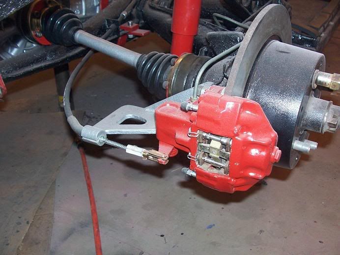 I am 99.9% sure they are 914 rear calipers. The rotors slide over a small hub that is drilled and tapped for the standard VW 4 bolt pattern. The hub is attached to the splined shaft on the axle. Can I get the hubs and rotors re-drilled for the chevy bolt pattern? Would I have to get the holes in the hubs and/or rotors welded shut? I think the hubs are cast iron. Any other suggestions other then narrower tires or re-drilled hubs? And no...new rims are not an option. Thanks for your help in advance. |
|
|
|
Post by jspbtown on Oct 6, 2011 18:09:17 GMT -5
Depending on how you use (or abuse) it it will handle all those engines. Lots of dropped clutch starts and serious abuse and it will break. Normal everyday spirited driving it will be fine with those motors (assuming its in good condition to start).
|
|
|
|
Post by jspbtown on Oct 6, 2011 14:31:45 GMT -5
No replacement for displacement. All those engines are nice. Any of them buitl correctly will give nice power and good economy.
The larger you get the more heat so you want to make sure you have good cooling. There is also machining that is required to build them all. Are you planning on building your single port? If so you may want to reseach what case yo have and how good of a foundation it will make.
More cubic inches=more power=more stress on internal components. You want the best case you can get for your foundation.
|
|
|
|
Post by jspbtown on Oct 5, 2011 14:53:25 GMT -5
Big money to convert and won't save you much $$ in costs when you consider fuel mileage from the VW and your short commute.
|
|
|
|
Post by jspbtown on Oct 5, 2011 14:28:32 GMT -5
CoFab shocks available at NAPA. Nice oil shocks. No gas.
Just order by type of beam. Ball joint go...say 1974. Link pin go...say 1964.
|
|
|
|
Post by jspbtown on Oct 2, 2011 14:54:32 GMT -5
I wish I had taken more "before" pics back then, but this should give you an idea of the condition it was in when I first got it. 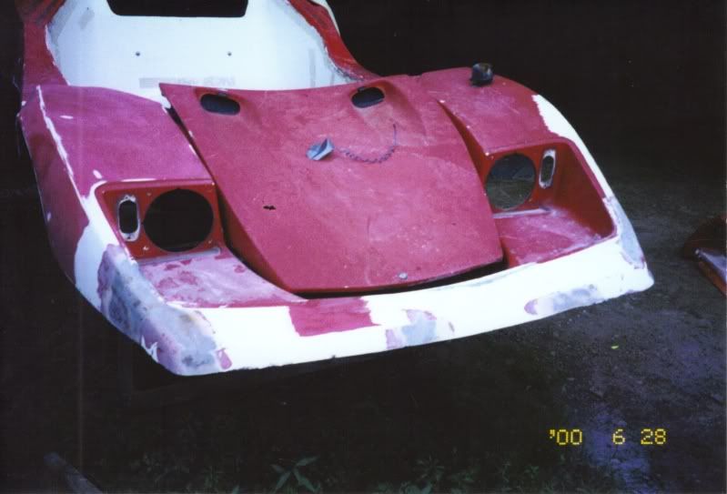 |
|
|
|
Post by jspbtown on Oct 2, 2011 14:33:31 GMT -5
Did someone say "Sterling"?: 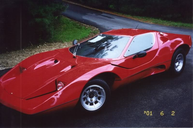 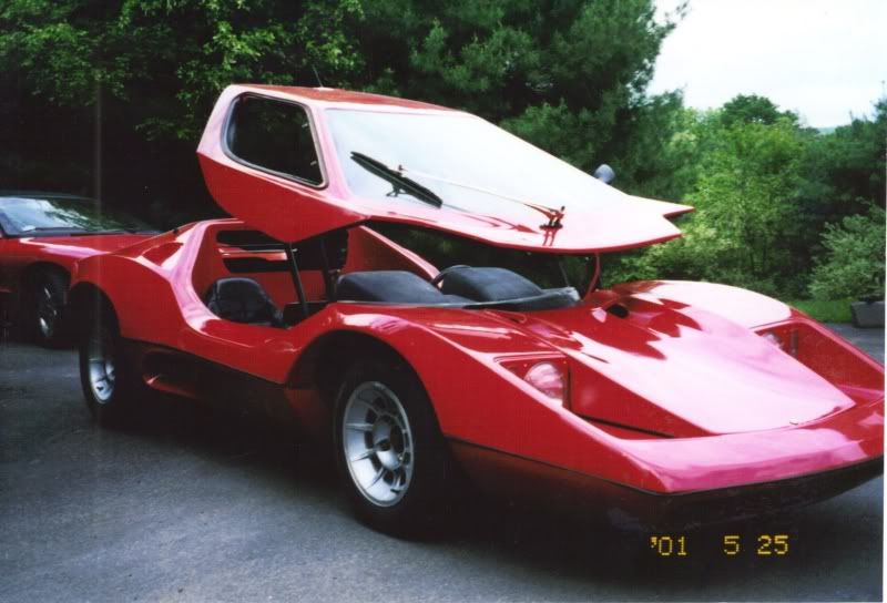  Built by me over 10 years ago ......Wow, time flies. |
|
|
|
Post by jspbtown on Oct 2, 2011 10:01:17 GMT -5
I have never seen a fully drivable one....despite many, many attempts.
|
|
|
|
Post by jspbtown on Oct 1, 2011 18:31:18 GMT -5
Like?
|
|
|
|
Post by jspbtown on Sept 18, 2011 18:01:08 GMT -5
Shocks control suspension rebound (so you don't go bouncy bouncy all the way down the street) but do nothing for ride height (air shocks and coil overs excluded). The suspension is so stiff because of the design and the lack of weight up front. Your back moves more because of the added weight back there.
You can add adjusters and make the suspension an almost progressive style. You can remove one set of torsion leaves and replace them with a through bar. Or you can remove a leaf or two in each torsion tube.
All are much more involved then lowering your tire pressure. 35lbs up front is way, way too much. Start at 18lbs. If your tire squeal around corners and it feels sluggish keep adding 2 lbs until you hit the sweet spot.
|
|
|
|
Post by jspbtown on Sept 18, 2011 13:09:45 GMT -5
An one of the easiest and cheapest ways is to play with your tire pressures. Knock them down to the high teens or low 20s. It will make a big difference.
After you do that there may be more involved things that can be done.
|
|
|
|
Post by jspbtown on Sept 17, 2011 13:20:12 GMT -5
Out this morning. I found 2 sockets. You should get it next week.
|
|
|
|
Post by jspbtown on Sept 16, 2011 21:34:33 GMT -5
Got your message. I will send the tach and any extra sockets I have out tomorrow.
|
|
|
|
Post by jspbtown on Sept 16, 2011 10:25:59 GMT -5
Well let me take a look at what I may have. How many do you need? if I have some I will thwo them in the box.
|
|
|
|
Post by jspbtown on Sept 15, 2011 20:53:18 GMT -5
I tried sending you a PM but my home computer wouldn't do it...not sure why. Here are the pics: 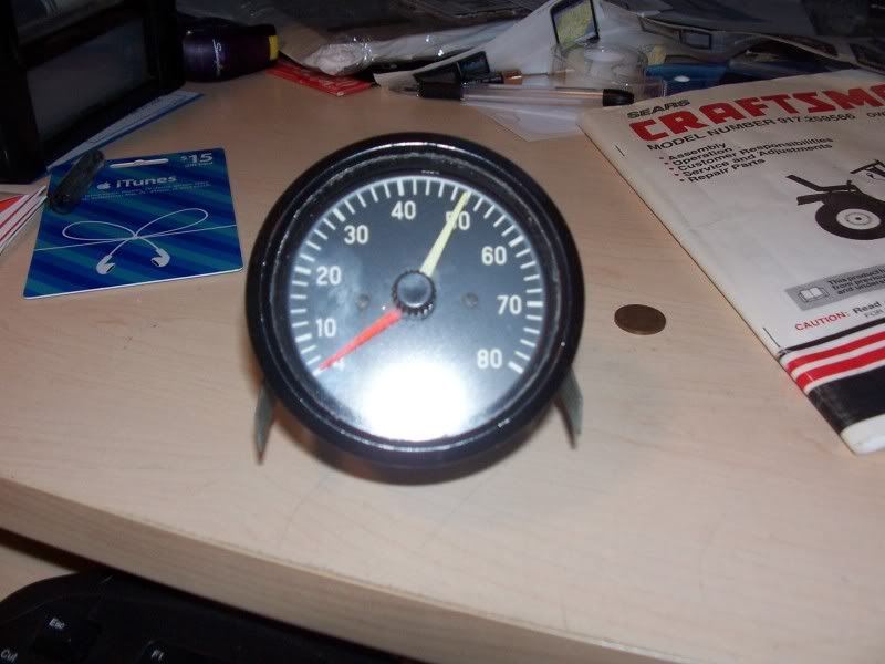 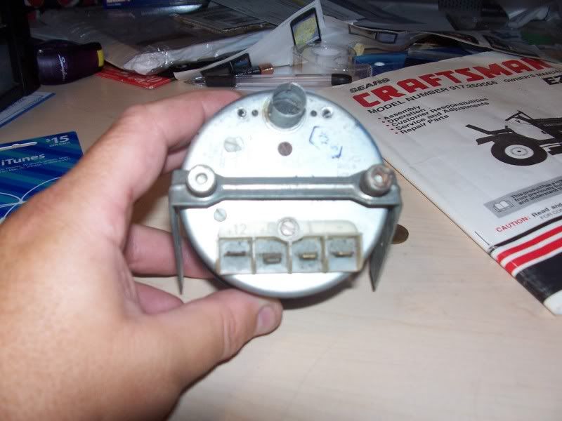 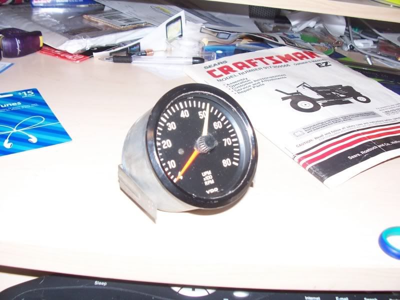 It came out of the orange Bradley I built so I bet it is spot on. Its 3 1/4 from outside edge to outside edge. On the back it has 4 tabs labeled +12, +6, 1 & -...just like yours. There are a couple of small paint chips on the bezel but no dents. The glass is scratch free. It has the mounting bracket and screws but no lamp socket. If you want it then PM me your address and I will send you mine. |
|
|
|
Post by jspbtown on Sept 15, 2011 13:20:35 GMT -5
Funny...the early Porsche (rear engine cars) had larger rear rotors then front....Wonder why?
Rotor Sizes F/R
911T 69-73 282x20 / 290x20
911S 69-73 282x20 / 290x20
Carrera RS 282x20 / 290x20
Carrera 74-77 282x20 / 290x20
911SC 78-83 282x20 / 290x20
930 Turbo 78-89 304x32 / 309x28
Carrera 3.2 84-9 282x24 / 290x24
As a very general trend with numerous exceptions, typical weight bias for an FR is 55/45 front/rear; for MR, 45/55; for RR, 35/65. Rear weight bias reduces forward weight transfer under braking, and increases rear weight transfer under acceleration. The former means that traction is more evenly distributed among all four wheels under braking, resulting in shorter stopping times and distances.
|
|
|
|
Post by jspbtown on Sept 15, 2011 11:15:46 GMT -5
Most cars have all the weight up front....thats why in most cases the fronts do the work (take a look at the disc/pad size from front to rear...MUCH larger up front). Brads however have much more weight in the rear. They need better breaking in the rear as the fronts will have a tendency to lock up from lack of weight (without appropriate bias control)
Another benefit of discs is they don't need adjustment.
|
|
|
|
Post by jspbtown on Sept 15, 2011 8:15:46 GMT -5
Money no option: Disc all the way around. Its a much more efficient braking system.
Money a concern: Drum brakes stop this lightweight car just fine.
|
|
|
|
Post by jspbtown on Sept 14, 2011 9:56:33 GMT -5
Your acting in the confines of a defined space. The only way you can get wider is to go higher (without extensive mods).
So the question begs...how tall are each of you?
|
|
|
|
Post by jspbtown on Sept 14, 2011 8:21:20 GMT -5
Working on getting out to the garage. My son has 6 games in 10 days so time is a little tight. Thursday night I will have info for sure!
|
|
|
|
Post by jspbtown on Sept 12, 2011 21:45:46 GMT -5
You need two sets of those right?
|
|
|
|
Post by jspbtown on Sept 12, 2011 21:43:55 GMT -5
You will need to do more than just molding it in. You will need to run steel up and around it.
|
|
|
|
Post by jspbtown on Sept 12, 2011 11:49:56 GMT -5
Thats my thinking...either 6 or 12 volt. If its old it might have been built right around the time when VWs were going from 6 to 12 volt.
My son has a soccer game tonight but I will try to get a picture of it with a measuring tape after the game.
|
|

