|
|
Post by vallyr on Mar 26, 2010 14:04:49 GMT -5
I have questions regarding both topics Pan dropping and body raises.
First pan drops.
A) I've heard of people affixing vw pans with sheet metal screws rather than spot welding them on. Have any of you tried it with reasonable results?
B) I make alot of medieval armour and use peened over rivets. Would they be a viable solution in your opinion?I'd think theyd be better than sheet metal screws atleast?
C) What kind of angle stock were you guys using in your drops?
Regarding Body raises
D) Some where on the forum or a linked site I saw some one put down an inch of closed cell foam on top of the _____(heater channel?) to raise the body. Would this kind of foam actually hold up to long use? If so any links?
E) Has any one else done a raise using other materials like metal?
F) Any adverse effects of raising the body related to visibility or body sag?
G) Lastly the seats in mine were bolted through a 2x4 right to the pan. If I raised the body and dropped the pan do you think it would be viable to remove the seat from my 71 brackets and attatch the bucket to that?
Also If youre using angle iron of sorts to form a new bracket to which the pan attatches to, I wonder if I could almost just make a bracket and then cut some 12gauge and use that for a pan rather then to mess with repairing mine?
|
|
|
|
Post by jspbtown on Mar 26, 2010 14:35:18 GMT -5
Lets see: A) I've heard of people affixing vw pans with sheet metal screws rather than spot welding them on. Have any of you tried it with reasonable results? - Never have used screws. I bought a welder to do my first set of pans. You could rivet them along the tunnel, but you may have some challenges along the front and rear sections. B) I make alot of medieval armour and use peened over rivets. Would they be a viable solution in your opinion?I'd think theyd be better than sheet metal screws atleast? - Yes...I think they would be better than screws. D) Some where on the forum or a linked site I saw some one put down an inch of closed cell foam on top of the _____(heater channel?) to raise the body. Would this kind of foam actually hold up to long use? If so any links? - Never heard of this and I don't think it would work. no..wait...it would not work. E) Has any one else done a raise using other materials like metal? - I have used composite decking. See picture below. F) Any adverse effects of raising the body related to visibility or body sag? - nope G) Lastly the seats in mine were bolted through a 2x4 right to the pan. If I raised the body and dropped the pan do you think it would be viable to remove the seat from my 71 brackets and attatch the bucket to that? - I don't know what kind of sliders you are referring to, but I would get the universal sliders for about $20 a pair. They will give you adjustability and only about 1 inch off added hieght.     |
|
|
|
Post by vallyr on Mar 26, 2010 15:13:09 GMT -5
Thats a crazy rear roof!
Could you give me some more information about your composite decking? also how far did you raise it with the decking?
|
|
|
|
Post by Gary Hammond on Mar 26, 2010 15:40:02 GMT -5
|
|
|
|
Post by vallyr on Mar 26, 2010 16:15:27 GMT -5
thanks, yeah i have the cd and was looking through it. as you may have guessed I was trying to look at a work around as the only welder i have access too would burn giant holes through sheet metal  those are great links though Much appreciated! |
|
|
|
Post by jspbtown on Mar 26, 2010 21:41:23 GMT -5
For the long sections I glued and nailed (using an air nailer with thin brads) together 4 pieces of composite decking and cut them to the correct shape with a jig saw. The same for the rear section (the parts that angle up from the floor toward the tunnel). The jig saw will cut right through the thin brads.
For the section that goes over the napolean hat I used a different method. I took a piece of poster board and carefully cut out the shape of the hat. I then used a simple compass (the kind with a sharp end and a pencil) and set it at 3". Tracing the cut line you have the exact shape of the piece you need. I then glued and nailed up some pieces in that rough shape and finished cut it with a jig saw.
I used the same basic process to form the rear semi-circular piece you need to attach the two rear sections. Its really not that hard.
I used liquid nails for decks for the adhesive.
The total lift was just a hair under 3"
|
|
|
|
Post by mrbigh on Mar 27, 2010 9:58:25 GMT -5
thanks, yeah i have the cd and was looking through it. as you may have guessed I was trying to look at a work around as the only welder i have access too would burn giant holes through sheet metal  those are great links though Much appreciated! Hi vallyr, another solution to the mod. I added a 3" lift made out of steel channel, already pre-cut and shaped in 4 pieces for the VW chassis. Readily available from VW aftermarket suppliers for about 100 bucks. This Kit is great and bolts down in a jiffy |
|
|
|
Post by vallyr on Mar 27, 2010 11:15:46 GMT -5
ahah i see it , a 3 inch empi kit, little pricy ut yea
|
|
|
|
Post by papasdoo on Mar 27, 2010 20:52:37 GMT -5
as for rivets n screws ember your tail is being suported by them you will be traveling at 60 plus at times over bumps n such if you check around your neighborhood im sure you can find someone who has a small mig welder and wold be wiling to help you out its like the racers say if you got a 20 dollar head put it in a 20 dollar helmit the skin on my tail is worth far more than that im sure yours is to and the body lift well wood or composit will work but ember the pan is the strongest part of your car protecting you from an impact the rest of it is the same material they use for cofins a little extra expence in the steal chanel is worth the strength and durability in my opinion
|
|
|
|
Post by robstone on Mar 28, 2010 11:50:40 GMT -5
|
|
|
|
Post by vallyr on Mar 28, 2010 20:33:56 GMT -5
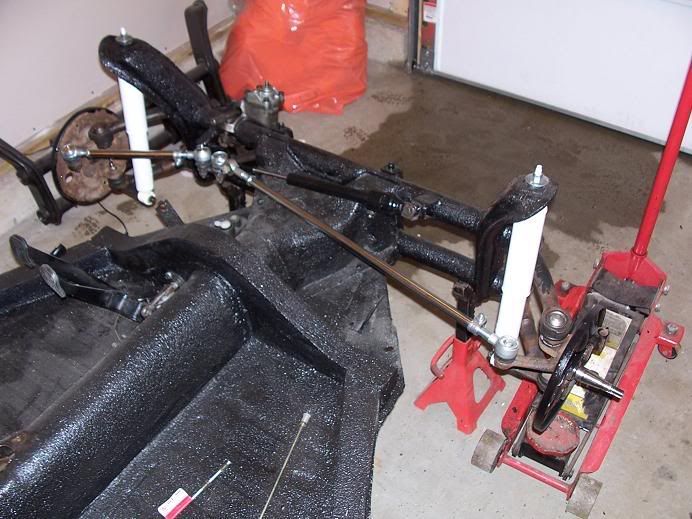
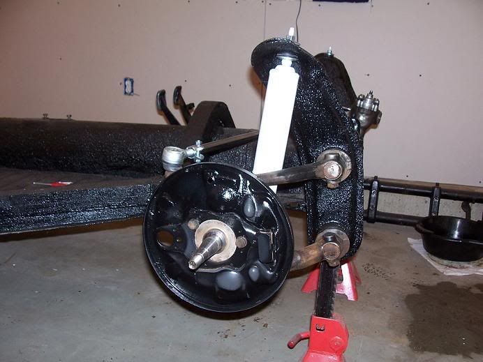
Hey rob. Those are awesome pictures! That is a super sweet pan and chassis! Couple of questions.
What kind of metal is that making the frame? Is that just angle iron or is it square tube steel. Cant tell.
The T in the middle of the pan is just a brace?
What gauge of sheet metal is that used?
Looks like you lowered the whole pan instead of just doing the angled drop like the manual shows. Is that correct?
How did you reattach the pedal cluster so its level with the lowered pan in the front?
How is the sheet metal holding up? See off hand I'd just assume since there isnt much indentation, flutes and ridges that it would want to bend? Does that support soak all of that up?
Lastly, you widened it? What is this intended to accomplish? Do the mount holes still line up with the fiber body?
|
|
|
|
Post by robstone on Mar 29, 2010 19:57:16 GMT -5
The edge is angle iron from Lowes.
The metal is 1/8 inch I believe.
I lowered the whole pan because I did not like the feeling of having my feet higher than my butt while driving a car. We will make custom pedal assembly when we start on it again.
Those Ts are braces to stop the warp sound when you step on the pan.
I widened the pan so I can put any seat width I like in it. Yep the holes don't line up. We are widenng the GT II's body mount flange too.
Once all welding (seat brackets and rear tilit framing) is done on the pan, we will POR 15 it again.
I have lots of fiberglassing to do, and I still have to make the tilit rear end framing on the chassis. Right now we are in a lull. Been kayaking instead.
I have a boatload of vids I can repost on the whole project. I can't seem to find any of them on here? I have a few threads on TheSamba message board for kit cars that have the vids but they have been buried way down the list.
|
|
|
|
Post by vallyr on Mar 29, 2010 21:06:39 GMT -5
Thanks Rob. Your project has inspired me! Instead of using composite decking I went to the local steel yard and bought 20 some odd feet of 3"x1-1/2" at 1/8 inch thick square tubing. Got my buddy to break out the stick welder and we started fabb'ing a body lift that might as well be a frame with a little added protection . We are making right over my spare junker chassis then we are going to move it to the actual bug pan later. Totally destroyed a our blade, so this stuff is pretty burly. About one and a half bolt holes arent quite aligned but im sure ill think of something Here are more pic's  A mock up on the pan    |
|
|
|
Post by Gary Hammond on Mar 29, 2010 21:08:51 GMT -5
|
|
|
|
Post by robstone on Mar 30, 2010 19:21:43 GMT -5
Hey thanks Gary! You'll have to check out our kayaks on Facebook.
Vallyr the thing to consider when raising the body location is the steering column and wiring under the dash. The steering column mounts to the body, so if the body is raised it is raised. The rag joint won't like it. You may have to obtain the two u-joint adapter shaft deal. The wiring may be tight already where it goes to the rest of the car. If you totally rewire then it should not be an issue. IMO
|
|
|
|
Post by robstone on Mar 30, 2010 19:29:23 GMT -5
Also you should ensure that your rotted frame/template is not warped, bowed, or sagging. If it is, your new fabbed tubing will be welded in the same exact shape. I would tack everything at first so it won't be too hard to undo welds and rework the metal if needed. I had to redo welds several times to get the frame just right. IMO
|
|
|
|
Post by vallyr on Mar 30, 2010 19:39:16 GMT -5
Yeah, my buddy, seen doing the welding, is an ASE certified for wiring. His idea was to go to the junkyard, steal some modern fuse setups for a couple of bucks and just rewire the whole thing.
I didnt think about the steering column though. Thanks for the tip there.
As far as fabing goes, our current plan is to weld the tubing into four separate sections, the hat, the sides, and the rear curve, then when we gut my beetle later, test mount it on its chassis and weld it all up.
The front hat just seems like a seal point since there are no bolts there, so I almost wondered if we could just weld the tubing to the chassis in the front and the rear and hang a custom pan from the top of the tubing and drop it down there sort of like a "U" with lip like wings on the top sides. heh.
|
|
|
|
Post by Jeff Troy on Mar 31, 2010 10:47:19 GMT -5
Hi, val,
Just a point, but may be useful to you as a caution.
The GT body is comprised of separate inner and outer shells. These were laid up in more than one mold, then joined. Some bodies ended up fitting the VW chassis better than others.
If mounted so the inner body seated perfectly on the frame, the outer shell of my GT body angled slightly to the right. This was most noticeable in a wider overhang over the right front tire, and barely any overhang at all over the left tire.
I corrected this by adding an extra layer of rubber gasket along the left side of the forward chassis hump. This causes the inner shell to sit more to the left, just enough to center the outer body over the tires.
This may not apply to the GTII, so Rob would not have addressed it.
BTW, Rob -- your stuff is always amazing. Great work!
Warmest...
|
|
|
|
Post by jspbtown on Mar 31, 2010 11:53:33 GMT -5
Jeff,
The Bradley GT I did suffered from the same issue. I mounted it up using the humps as my reference points...big mistake! It was off about 3/4" from side to side. Not amazingly noticeable as you only look at one side at a time...but not satisfactory for me. It was a pain to re-center it after is was almost completed.
|
|
|
|
Post by Jeff Troy on Mar 31, 2010 15:06:44 GMT -5
Hi, Jeff,
Yeah. I didn't really understand what was going on or how to fix it until my third restoration in 1994. Once I nailed it to the misalignment between the inner shell and the hump, the fix was easy.
I used extra rubber gasket to push the body over because I don't weld and it seemed like the easiest way to do the job in small increments if my judgment was off.
BTW, your stuff always looks great. Steadily impressed!
Warmest...
|
|